|
DIGITAL
RECORDING:
In digital
recording, rather than setting up an
analogy to represent the signal parameters, we
represent their instantaneous
values as a series of numbers or digits. These
numbers can be stored on
tape or disc, then later used to reconstitute the
original signal.
In English we call this a
digital system, but this is
really a misnomer. It is in fact a numerical
system. In French --
numérique.
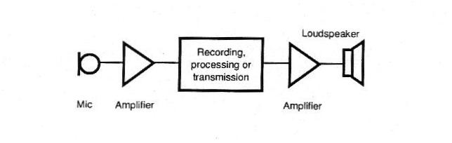
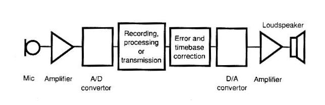
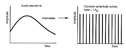
The signal to
be recorded is processed by an Analog to
Digital Converter (ADC).
We sample or measure
the signal often enough to get a
smooth representation of its shape.
Sampling theory dictates that we must
sample at a minimum of twice the highest
frequency we want to represent. For
professional audio, we consider the
highest frequency to be 20 kHz; so we have
to sample at a minimum rate of 40,000
samples per second.
- For compact disc,
the sampling frequency is 44,1000
times per second or 44.1
kHz.
- In digital video
systems we use
48 kHz sampling for the sound signal.
|
|
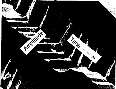
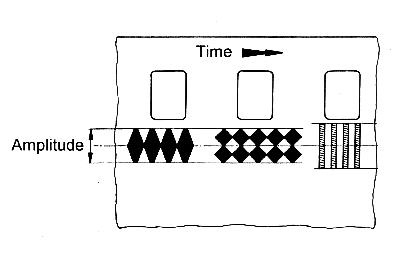
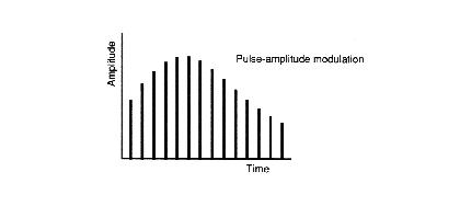
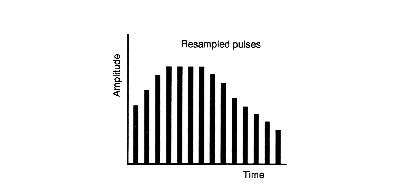
This sampling
gives a series of pulses whose amplitude
changes with the amplitude of the
original signal.
|
|
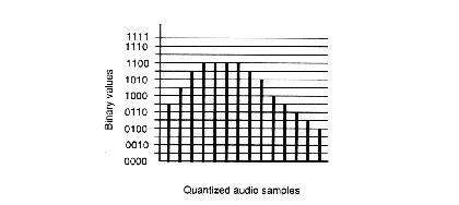
The amplitude
of each pulse is measured and converted into
a number. For CD and
DAT, these numbers are represented by 16 binary digits or
bits.
A 16-bit number can
represent 65,536 different levels or steps
of
amplitude. Digital signal processors and
consoles use 24 or 32 bit
numbers internally to minimise errors.
Each bit represents 6dB
of dynamic range i.e. 16 bits offer 96dB
dynamic range (compared to your ears' 120
dB.)
|
|
These numbers
are then stored on hard disk or in flash
memory. Extra data may be included to
permit
detection and correction of errors, and to
identify the individual
recordings. On playback, the extra
information is stripped off.
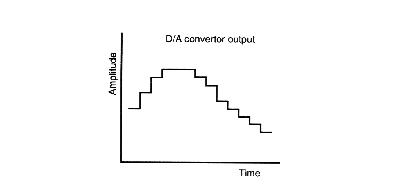
On playback, the
sampled numbers are passed to a Digital
to Analog Converter (DAC) which
reconstitutes the basic shape of the
wave.
|
|
As you can
see, the shape is rather jagged,
because the individual steps are wider
than the original sampling pulses,
representing a false time value. The
DAC output is resampled as shown below.
|
|
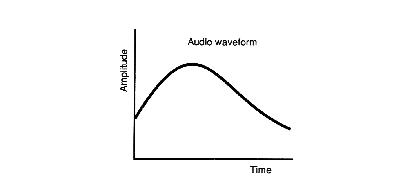
The pulses are
passed through a filter which removes all
frequencies above 20 kHz.
This restores the smooth shape of the
original signal. This is the signal
which appears at the analog output of the
recorder or CD player.
|
|
The standard settings for Compact Disc or
"CD Quality", Windows PCM (wav) audio
are :
- stereo (2 channels
left/right)
- 44,100 samples per
second/channel (44.1 kHz)
- 16 bits per sample (65,536
steps -- dynamic range 6dB/step, 96 dB
total.)
|
|
|
Digital vs Analog:
|
Dynamic Range: the ratio of the level of the loudest to the softest sound that can be reproduced -- usually expressed in decibels (dB)
In an analog system, the level of the loudest sound is limited by the onset of distortion -- due to the physical limits of the media. The level of the softest
sound is limited by the background noise -- scratches and dirt on film
or disc, the composition of the magnetic material on tape.
In a digital system,
the dynamic range is defined by the number of digital bits used
to represent the sampled audio -- each bit is equivalent to 6dB
of dynamic range.
|
| Medium |
Peak:Noise Ratio |
Dynamic Range |
Equivalent Digital |
| Analog Optical (Film) |
256:1 |
48 dB |
8 bits |
| Analog Disc (Vinyl) |
1,000:1 |
60 dB |
10 bits |
| Analog Magnetic (Reel to Reel) |
4,000:1 |
72 dB |
12 bits |
| Digital (CD) |
65,536:1 |
96 dB |
16 bits |
| Real World (Human Ear/Brain) |
1,000,000:1 |
120 dB |
20 bits |
| Professional Digital (Scarlett 2i2/Reaper) |
16,000,000:1 |
144 dB |
24 bits |
|
Frequency Response: the range of frequencies that can be reproduced -- usually expressed by the upper frequency alone.
In an analog system,
the upper frequency is usually set by the speed of the media and
the physical dimensions of the stylus, optical slit or magnetic gap.
In a digital system, the upper frequency is set by the digital sampling frequency -- the upper limit is one-half the smapling frequency.
|
| Medium |
Sampling/Speed |
(Upper) Frequency Response |
| Analog Optical (Film) |
60 micron slit/ 45.7 cm/s |
8,000 Hz |
| Analog Disc (Vinyl) |
19.8 micron stylus/ 19.8 cm/s |
10,000 Hz |
| Analog Magnetic (Reel to Reel) |
20 micron gap/ 38.1 cm/s |
20,000 Hz |
| Digital (CD) |
44,100 Hz |
22,000 Hz |
| Real World (Human Ear/Brain) |
n/a |
20,000 Hz |
| Professional Digital (Scarlett 2i2/Reaper) |
96,000 Hz |
48,000 Hz |
Notes:
- 45.7 cm/s (18 inches/s) -- 35 mm film speed
- 38.1 cm/s (15 inches/s) -- 1/4 inch analog master speed
- 19.8 cm/s (7.5 inches/s) -- roughly linear speed of 7 inch, 45 rpm vinyl disc
|
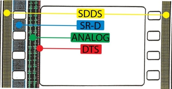
Digital Film Sound Formats:
SR-D -- Dolby Digital (5.1 channels)
SDDS -- Sony Dynamic Digital Sound (7.1 channels)
DTS -- Digital Theatre Systems (time code linked to external optical media -- 5 channels)
ANALOG -- Dolby analog with Spectral Recording noise reduction (4 channels)
|