|
|
SOUND
II |
|
M-AUDIO
FAST TRACK PRO |
|
|
|
|
|
|
SOUND
II |
|
M-AUDIO
FAST TRACK PRO |
|
|
|
|
|
|
|
|
|
|
|---|---|
|
1 |
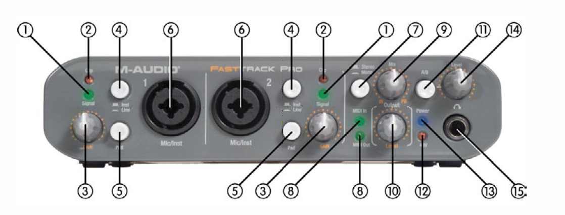
SIGNAL LED – When lit, this LED indicates the presence of an audio signal at the associated Inst/Line input. |
|
2 |
CLIP LED – When lit, this LED indicates too hot an input signal at the associated Mic/Inst input. The LED will light when the signal is 3dB below the clipping point. |
|
3 |
INPUT GAIN LEVEL – This potentiometer controls the input level of its associated analog Mic/Instrument/Line input. |
|
4 |
INST/LINE SELECTOR – This button selects the input level of the front panel 1⁄4” inputs. In the OUT position, the inputs are set to accept an instrument level signal (such as that from a guitar or bass) while in the IN position they are set to accept a line level input (such as that from a keyboard or drum machine). Please note that the XLR input level is unaffected by this switch. |
|
5 |
PAD – With this switch in the IN position, a –20dB pad is inserted into the input circuit, lowering the input level. Use this pad when the input level of your analog signal is too hot (as indicated by illumination of the Clip LED (2)), even with the GAIN knob (3) at or near minimum. |
|
6 |
INST/LINE INPUTS – These Neutrik hybrid connectors will each accept a low-impedance mic level signal on a standard three-pin balanced XLR or TRS plug, or a high-impedance instrument level signal on an unbalanced 1/4” TS plug. |
|
7 |
STEREO/MONO BUTTON – This button toggles the direct input monitoring between stereo and mono operation. In Mono mode, an input will be heard equally in the left and right of the headphones. In Stereo mode, input 1 will be heard in theleft while input 2 will be heard in the right. |
|
8 |
MIDI INPUT/OUTPUT LEDs – These LEDs display MIDI input and output activity. They will light whenever MIDI data is seen at the rear panel MIDI output (20) or MIDI input (21). |
|
9 |
INPUT/PLAYBACK MIX LEVEL KNOB (MIX IN, PB) - This knob controls the audio mix sent to the Line Outputs, fading between the input signals (input monitoring) and the output signal from your audio application software. When turned fully counter-clockwise (IN position), only the input signals are heard at the line outputs. When turned fully clockwise (PB position), only the output signalfrom your DAW software is heard at the line outputs. |
|
10 |
OUTPUT LEVEL KNOB (OUTPUT LEVEL) – This knob controls the signal level at the 4 analog line outputs. This control is independent from the Headphone Level knob (14). |
|
11 |
A/B MONITOR SELECTOR BUTTON (A/B) – This switch selects the output source sent to the Level knob (14). In the A (out) position, the main line output signal is sent to the headphone outputs. In the B (in) position, the signal assigned to the S/PDIF output is sent to the headphone outputs. |
|
12 |
PHANTOM POWER INDICATOR LED (48V) – This LED lights to indicate the presence of 48V phantom power at the front-panel XLR inputs, as activated by the rear-panel Phantom Power switch (22). NOTE: While most modern dynamic microphones are unaffected by phantom power, many ribbon mics and some older dynamic microphones may be damaged if phantom power is applied to them. |
|
13 |
POWER INDICATOR LED (POWER) – This LED lights when the Power switch (16) is activated, with the unit receiving power from either the host computer’s USB bus, or from the (optional) external power supply. |
|
14 |
HEADPHONE LEVEL CONTROL - This knob controls the output level to the Headphone output (15). It is independent of the main Output Level control knob (10). |
|
15 |
HEADPHONE
OUTPUT – This is a 1⁄4” stereo TRS
jack, designed to drive a pair of stereo headphones. The output
level is controlled |
|
|
|
|
16 |
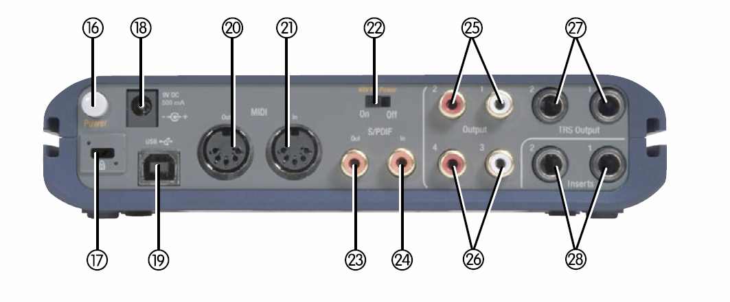
POWER SWITCH – Pressing this button will power on the Fast Track Pro, illuminating the front-panel Power LED (13). The unit must be connected to a functioning host computer’s USB bus, or to the optional external power supply. |
|
17 |
KENSINGTON LOCK PORT – This connector is compatible with Kensington® security cables to protect your device from theft. |
|
18 |
POWER
SUPPLY CONNECTOR (9V DC 500 MA) – Connect
the optional 9V DC 500mA power supply to this jack when using the
Fast |
|
19 |
USB INPUT (USB) – Connect a standard USB cable to this port, connecting the other end to your host computer. |
|
20 |
MIDI OUTPUT (MIDI OUT) – Connect to the MIDI input of your controller or other MIDI device. |
|
21 |
MIDI INPUT (MIDI IN) – Connect to the MIDI output of your controller or other MIDI device. |
|
22 |
PHANTOM POWER SWITCH (48V PH POWER) – Sliding this switch activates the phantom power circuitry, sending 48V power to the front-panel XLR inputs for use with condenser microphones requiring external power. |
|
23 |
S/PDIF OUTPUT (S/PDIF OUT) – Digital output on coaxial (RCA-type) connector. The S/PDIF Out is activated by selecting outputs 3 and 4 in the Control Panel. The S/PDIF output signal is duplicated on Outputs 3 and 4 (26). This output will also support pass-through of AC-3 or DTS encoded surround formats. NOTE: When AC-3 or DTS encoded signals are passed through this output, all analog input and output will be muted.
|
|
24 |
S/PDIF
INPUT (S/PDIF IN) – Digital
input on coaxial (RCA-type) connector. This input will accept
digital input signal at any of the |
|
25 |
UNBALANCED
OUTPUTS 1 AND 2 (OUTPUTS 1/2) –
These are unbalanced outputs on RCA connectors. The output signal
to these jacks is controlled |
|
26 |
UNBALANCED
OUTPUTS 3 AND 4 (OUTPUTS 3/4) –
These are unbalanced outputs on RCA connectors. The signal to
these connectors |
|
27 |
BALANCED
OUTPUTS 1 AND 2 (TRS OUTPUTS 1/2) –
These are balanced 1⁄4” TRS jacks. The output signal
to these jacks is controlled |
|
28 |
INSERTS 1 AND 2 (INSERT 1 / INSERT 2) – These 1⁄4” TRS jacks are configured to connect to an analog outboard effect (compressor/limiter, delay, reverb, etc.), inserting the effect between the preamp and the A/D converter. These inserts are only active when a connector is inserted, and are otherwise bypassed. NOTE: The TRS jack is configured as follows: Tip=Send; Ring=Return; Sleeve=Ground.
|