|
|
SOUND 1 |
|
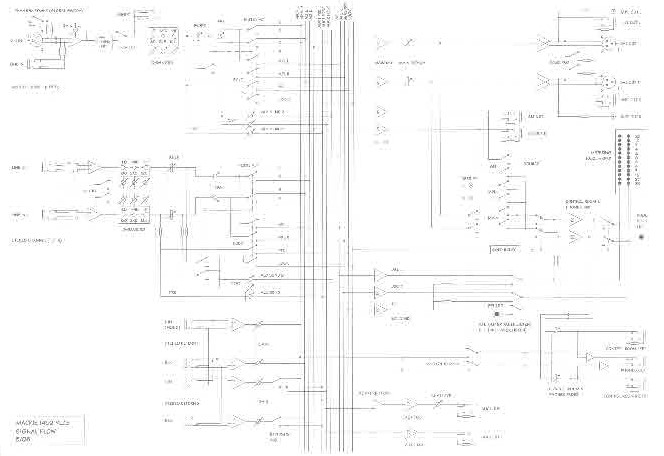
MACKIE 1402-VLZ3 MIXER |
|
|
|
|
|
|
SOUND 1 |
|
MACKIE 1402-VLZ3 MIXER |
|
|
|
|
INTRODUCTION: |
|
There are many terms used to refer to the complicated-looking piece of electronic gear sitting on the table in front of the Sound Booth window: console, mixer, mixing
board, sound board, mixing desk, sound desk.
[I
will try to be consistent and to always refer to the
mixer. If I slip up, you now know the
other possible terms.] In a
performance space, the
mixer serves to send the various sound sources
(microphones, CD players or FX units) to various
loudspeakers on the stage or throughout the house. It
allows you to control where the sounds will be heard
and how loud they will be. |
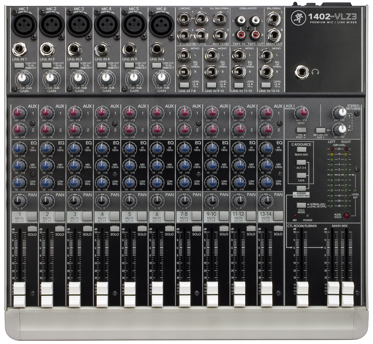 |
MACKIE 1402-VLZ3 MIXER: In a
sound system, a source of sound is referred to as an output.
A destination is referred to as an input.
Building a sound system involves connecting sources to
destinations -- an output to an input to
an output to an input.....and so on.
The sources could be the outputs of mics. on stage, CD players, effects units or tracks from a computer. The
destinations could be the inputs of the House speaker
system, onstage monitors, headphone amps or effects
units. The
MACKIE 1402-VLZ3 mixer allows you to simultaneously
control and send, any (one or more) of fourteen sound
sources to either of two main destinations; the
MAIN MIX,
and/or to either of two auxiliary destinations;
the AUX1-2
outputs. In a
sort of technical short-hand, this mixer may referred
to as a 14:2 mixer (with 2 auxiliaries) to indicate it
offers 14 inputs, and 2 main outputs (with 2
auxiliaries). Although
the mixer may appear to be complicated, it is in fact,
composed of only a few different building blocks,
called modules or strips.
Each type of strip groups
together all the controls and internal circuitry to
perform similar functions. On this mixer, there are two kinds of INPUT strips, 6 MONO and 4 STEREO. The INPUT strips are grouped together on the left side of the mixer. The MAIN strip is on the bottom right. The MONITOR and AUX MASTER strips are located above the MAIN strip. You
will only need to learn the operation of these few
strips, MONO INPUT
STEREO INPUT MAIN OUTPUT MONITOR OUTPUT AUX MASTER OUTPUT in order to "master" operation of the entire mixer. We'll
have a look at the front panel controls and the signal
flow through each of the modules in turn.
|
| MONO INPUT |
STEREO INPUT |
MAIN/MONITOR/AUX |
 |
 |
 |
| MONO INPUT STRIP |
||
|
|
||
|
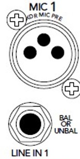
Audio signal levels fall into one of two categories. Microphones,
electric guitars and other electronic instruments
generate very low level signals; on the order of a
few millivolts -- thousandths of a volt. These are
called microphone
level signals.
Tape recorders, CD players, FX units and most other professional studio equipment, all generate much higher signal levels -- several tenths of a volt or more. These are called line level signals. There is a difference of 40 or 60 decibels (dB) between microphone level and line level signals. Either type of signal must be connected to the mixer via the appropriate jack or socket. Connecting a line-level output to a mic-level input will result in distortion. Connecting a mic-level output to a line-level input will result in an unusably low (quiet) signal. Microphone level signals connect to the three-pin XLR-type female connectors. Line level signals connect to the 1/4 inch TRS jacks. DO NOT connect signals to both sockets on the same input channel. |
 |
|
|
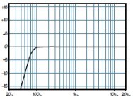
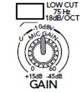
LOW CUT (High Pass Filter):
|
 |
 |
|
The "GAIN" control allows you to adjust the input strip so that you can operate with the white channel fader in its normal range, around "-U-" on the scale. ("U" stands for UNITY gain -- no amplification.) This assures that the signal will have the maximum headroom and minimum noise. (See "SOLO" button below.) Headroom is the level difference available between normal level and the point of distortion. Noise is the background hiss you hear when you turn the gain or volume up too much. |
||
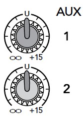
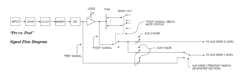
The controls labeled
"AUX" allow you to send a part of the signal from any
input channel strip to any of six additional outputs.
These outputs can be used to feed a separate mix to
program sound, monitors onstage, headphones in the
studio, or to the sound processing and effects devices
in the control room.
AUX
sends can be taken before or after the channel
fader. We call these feeds PRE fader or POST
fader. POST
fader sends are used to feed reverb devices where you
would want the strength of the reverb effect to follow
the level as controlled by the channel fader. PRE
fader sends are for feeding headphones for instance.
You wouldn't necessarily want the mix in the
headphones to change as you trim the recording or
house levels.
On the MACKIE 1402VLZ3:
AUX
1 SEND can be either PRE or POST. (see AUX1 MASTER
below.)
AUX 2 SEND is always POST. |
 |
|
 |
||
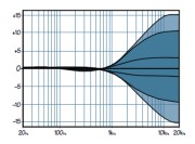 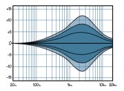 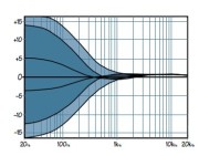 |
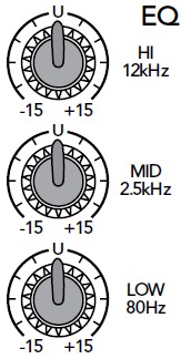
HIGH: ShelvingMID:
LOW: Shelving |
 |
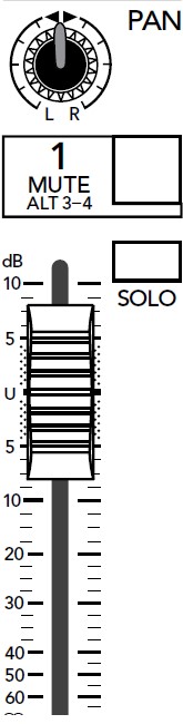
The "PAN" control (short
for panoramic potentiometer) allows you to send the
signal anywhere in the sound field between the
left and right outputs.
The "MUTE/ALT3-4" button has a dual function on this mixer.
Odd numbered outputs are arbitrarily considered as left and the even numbered ones as right. If you depress the "MUTE/ALT3-4" button and pan fully left; the signal will go only to ALT3. Panning right will assign the signal to ALT4 only. Midway between left and right will assign the signal somewhere between ALTs 3 and 4. The "SOLO" button sends the input signal directly to the left/right meters and monitor speakers (or headphones) and illuminates the large red indicator labeled "RUDE S0L0". These meters have much greater resolution than the four LEDs on the input channel. With "SOLO" in, start with the "GAIN" control fully counter-clockwise. As someone talks into the microphone or while you play the loudest cut of your show CD; rotate "GAIN" until the meters are just reaching the -0- VU point. They should never go higher than +7 Don't forget to release the "SOLO" button afterwards! (Look for the "RUDE S0L0" light.) The white sliding control is the input channel fader. This is your operational control over the signal level during a recording or performance. It allows you to smoothly fade an individual sound in or out. At the "-U-" setting of the channel fader, there is still 10 dB of gain available, should the input signal drop in level. We say that there is 10 dB of gain-in-hand. This gives you room to maneuver should the input signal change. Working at "-U-" on the channel fader also allows for smooth fades in or out. |
 |
|
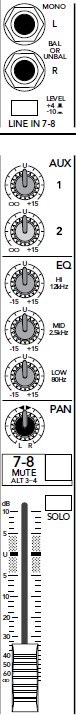
| STEREO INPUT STRIP |
||
|
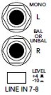
Line
level audio signal levels fall into
one of two categories. The LEVEL button
allows you to select the right amount of gain for the
source. It is the coarse equivalent of the GAIN
control on the STEREO line inputs. +4 -- Professional line level -- professional CD or DVD players, keyboards, effects processors or computer audio outputs. These are usually on XLR or TRS connectors. The electrical signal is nominally 1.23 volts (V). -10 -- Consumer line level -- consumer CD or DVD players, keyboards, effects processors or computer audio outputs. These are usually on RCA connectors. The electrical signal is nominally 100 millivolts (mV). |
 |
|
|
The rest of the controls
on the STEREO Input Strip are identical to those on
the MONO Strip.
|
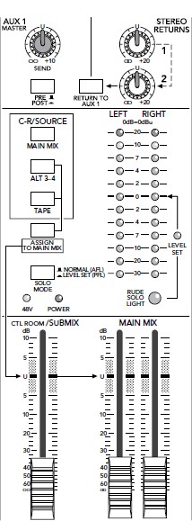
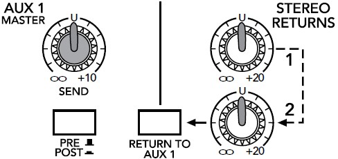
| AUX MASTER STRIP The AUX1 MASTER controls
the loudness of signals sent to the AUX1 SEND bus.
The AUX1 MASTER PRE/POST button allows AUX 1 SEND to be either PRE or POST. AUX 2 SEND is always POST on the MACKIE 1402VLZ3. The STEREO RETURNS 1/2
controls allow you to send the stereo outputs
(returns) of two separate external effects processors
to the MAIN MIX outputs.
RETURN TO AUX 1 button allows STEREO RETURN 2 to be sent to AUX SEND 1. |
 |
|
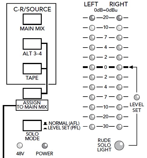
| MONITOR STRIP The C-R/SOURCE buttons
allow you to monitor (listen to) different signals on
the control room monitors.
The ASSIGN TO MAIN MIX button will send the ALT 3-4 and/or TAPE signals to the MAIN MIX bus. The SOLO MODE button determines how the individual SOLO buttons on the Input Stips will function --
When any SOLO button on
the console is depressed, the "RUDE SOLO LIGHT" will
flash to indicate this condition. Some condenser or electret type microphones can be powered externally, eliminating the need for batteries. The power required can be supplied by the mixer via the same cable used to carry the microphone signal to the mixer. This system is called phantom powering. The "48V" LED
indicates that 48 volt PHANTOM POWER
has been applied to all 6 of the MONO microphones
sockets by the rear panel "PHANTON ON" switch.
|
 |
|
|
In
certain cases, supplying 48 volt power to a
microphone or instrument not requiring it , may
result in noise or hum (at best) or damage to the
microphone or instrument (at worst).
Phantom powering should only be activated if you know you need it for a given device. |
||
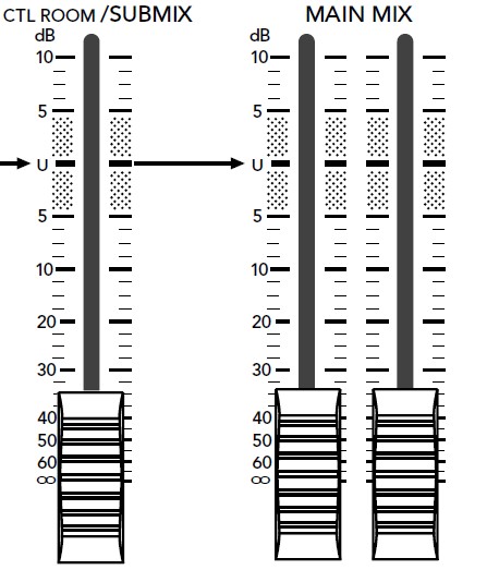
| MAIN OUT STRIP The CTL ROOM / SUBMIX
fader controls the loudness of the control room
moniotrs. If the ALT 3/4 bus is used as a submaster,
then this fader controls how much of the submaster mix
is mixed into the MAIN outputs.
The "MAIN" faders control the loudness of the signals from the MAIN left and right outputs. |
 |
|
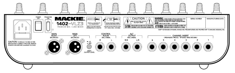
| REAR PANEL CONNECTORS |
||
 |
||
|
MAIN LEFT/MAIN RIGHT --
connect main (FOH) speakers here.
CONTROL ROOM -- connect control room (booth) monitors here. ALT OUTPUT -- connect alternate (ROH) speakers here. Input channel MUTE switches will send signals here. CHANNEL INSERT -- allows you to insert external processor (feedback suppressor, compressor or EQ) on each of Channel 1-6. |
||
|
|
||
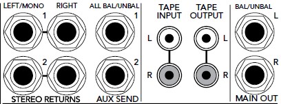
| FRONT (TOP) PANEL CONNECTORS |
||
 |
||
|
STEREO RETURNS -- connect
outputs of external effects
processors here.
AUX SEND 1/2 -- connect inputs of external effects processors or monitors here. TAPE INPUT/OUTPUT -- connect external recorder here. MAIN OUT -- same signal as rear panel XLRs but on TRS connectors. |
||