|
|
Michael Drolet -- 2008 |
| Home | PRODUCTION INTERCOM SYSTEM |
| |
|
|
|
Michael Drolet -- 2008 |
| Home | PRODUCTION INTERCOM SYSTEM |
| |
|
| CONTENTS: |
|
|
| INTRODUCTION: |
One of the tasks usually relegated to the Sound Dept. (by default) is the setting up of the Headset or Intercom system for the production. The intercom (INTERCOM-munication) system allows members of the production crew to communicate privately during rehearsals and performances, without disturbing the cast or audience. A minimal system consists of one Main Station , two beltpacks and associated cabling.
|
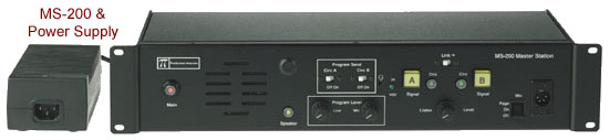 Figure 1 -- MS-200 Main Staion |
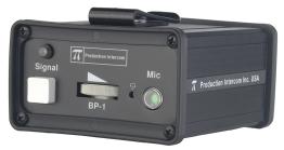 Figure 2 -- BP-1 Single Channel Beltpack |
|
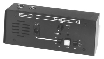
Figure 3 -- LS-3 Single Channel Speaker Station |
INTERCONNECTIONS:
The rear panel of the Main Station has three 3-pin male XLR connectors for each intercom line A and B.These connectors are wired in parallel. Any single-channel station or channel of a multi-channel station connected on a line plugged into Channel A of the a Main Station will be "party-lined" with all the other stations on that channel. In a multi-channel system, the goal is to assign specific people to the correct group, i.e. the other people they need to be in contact with the most. This is particularly important when the party line users are on a single-channel beltpack or station; less so if they are on multi-channel stations.
The pinout of the intercom connectors is as follows:
Pin 1 Ground (Shield) Pin 2 Power (+30 VDC) Pin 3 Audio Headset Connector:
The headset connector is located on the front panel of all stations. Production Intercom headsets are recommended, but others can be used if they meet the following requirements:
Mic Type --- Dynamic; 150 to 250 ohms impedance; -55 dB output levelHeadphone --- Dynamic; 50 to 2000 ohms impedance
The wiring of the headset is as follows:
Pin 1 Mic common Pin 2 Mic hot Pin 3 Headphone common Pin 4 Headphone hot
The mic and headphone wiring in the headset cord must be individually shielded. Do not connect Pins 1 and 3 together. Headset extension cords or headset "Y" cables are not recommended because they will increase crosstalk between channels.Paging Output:
The Main Station has a 3-pin Combo XLR/ female connector on the rear panel to feed into a studio PA (Public Address) system. Placing the front panel "MIC" switch in the "Page" position sends the signal from the headset microphone to the "Paging" connector. Program audio feed to the Announce Output is selected by setting a jumper on the Main board to the ON position.
The pinout of the "Paging Output" connector is as follows:
Pin 1 Sleeve
Ground (Shield) Pin 2 Tip
Hot (+) Signal Pin 3 Ring
Cold (-) Signal
The audio output is balanced and transformer isolated. It has a 600 ohm impedance and a nominal output level of 0 dBv. A shielded twisted pair cable should be used in the cable wired to this connector.
INTERCOM ETIQUETTE:
- Announce clearly that you are going "off headset", so the Stage Manager is aware.
- Turn off your mic., so it won't pickup ambient noise and interfere with communication.
- Turn your headset volume to minimum, so the headset feed will not distract the actors or audience.
- computer monitors
- electric motors
- lighting patch panels
- dimmer packs
TYPICAL THEATRE INSTALLATION:
Figure 5 -- Typical Theatre Installation Using Program Input
| BLOCK DIAGRAMS: |
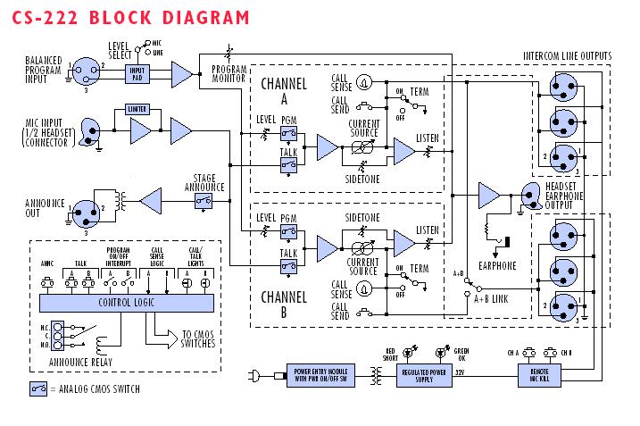
|
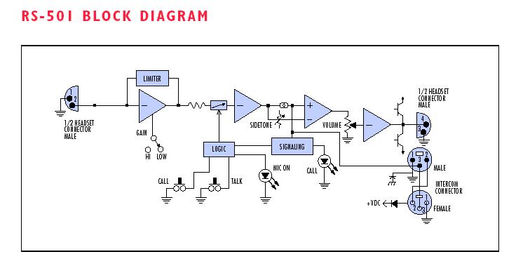 Figure 7 -- Cleacom RM-501 Beltpack Block Diagram (similar to Production Intercom BP-1) |
| TROUBLESHOOTING: | ||||||||
|
||||||||
| Problem: System does not operate. No power to Main Station or Power Supply. Green 24 VDC LED not illuminated. | ||||||||
|
||||||||
| Problem: Hum or buzz in system. | ||||||||
|
||||||||
|
||||||||
|
Problem: System feedback (Acoustical) . |
||||||||
|
||||||||
| Problem: Excessive crosstalk. | ||||||||
|
||||||||
| Problem: Program signal sounds distorted. | ||||||||
|
||||||||
| Problem: Call signals do not function. | ||||||||
|
Ambient Noise: Those background sounds which are not part of the specific communication but are picked up by the microphone. Selection of a good "noise-canceling" mic will reduce ambient noise.
Belt Pack: A portable electronics package worn on the belt or mounted on a wall or other convenient location. Interconnects to system with mic cable and is powered by a central Power Supply or Main Station.
Bridging, High Impedance (hi-Z): A method of connecting to an audio line (such as Clear-Com) with-out loading or taking appreciable power from that line. Simply stated, as you add more and more sta-tions to the line, the volume remains constant.
Call Signaling: This feature is included with the majority of Clear-Com products. It is a visual indica-tor on a station (a lamp or LED) used to attract the attention of an operator who has removed the headset.
Channel: A channel is the line that connects parties together within a party line - it is a two-way talk path. For example, if you have six people who need to hear one director, you have a seven-station single-channel need. If the same director needs to speak privately to any one of the six, add a second channel. You now have a seven-station, two-channel system.
Closed-Circuit: Any intercom which is connected via cable (also called hard-wired). The other type would be Wireless. . .we make those too. However, if you want privacy and versatility, you probably want a closed-circuit system or a combination of both.
Cross Talk: Leakage of audio transmissions from one channel to another.
Dry Pair: A telephone term is used to describe a pair of wires (2 conductors) that carry audio but no voltage. Contrast this with a "Wet Pair" that carries both audio and voltage.
Duplex: Duplex refers to bi-directional communications. Normal communication between individuals talking face to face is "full duplex" -- in other words you can talk and listen simultaneously. The alter-native is "half-duplex" such as a push-to-talk situation where one station at a time can talk while others listen. A walkie-talkie is a good example of half-duplex communication.
EFP: Electronic Field Production. An EFP truck contains the necessary audio, video, intercom, and other equipment to create these productions.
ENG: Electronic News Gathering. An ENG truck contains the necessary audio, video, intercom, com-munications, and other equipment to effectively support gathering news and transmitting news reports back to a studio.
IFB: The term means "Interrupt Fold Back." A Fold-Back is a monitor system that allows, for example, talent to hear their voices or musicians to hear their voices and instruments on stage. IFB (program in-terrupt) disconnects the audio source while the talk button on the Main Station is pushed.
ISO: A private conversation path. An ISO channel allows one to simply push a button and transfer themselves and the person they wish to speak with to an isolated channel.
Linking: Linking ties separate channels into one single party line.
Main Station: This is a product that includes both the ability to communicate with multiple channels without connecting them together, and to power all the stations connected to these channels.
Master Station: A Remote Station which requires AC power to operate, and cannot power other stations.
Multi-Channel: More than one channel
Paging Output: Redirects output of the Main Station's microphone to an external destination (such as a PA system).
Party Line (P.L.): Intercom system where all people talking on the system can talk or listen to each other simultaneously. Also called conferencing.
Point to Point: One path to one person.
Program: Audio source that is fed into the intercom channels.
Program Interrupt: Disconnects the audio source while the talk button on the Main Station is pushed. (IFB)
Remote Mic Kill (RMK): The ability for certain Main Stations to shut off all microphones on beltpacks in a system.
Remote Station: Like the belt pack, this would be any of the products connected to the intercom line that allow duplex or half-duplex conversation, but do not contain a Power Supply.
Sidetone: This is your own voice heard in your earphone as you are speaking.
Station: A station is connected to one or more channels. For example, if you have six people who need to hear one director, you have a seven-station single-channel need. If the same director needs to speak privately to any one of the six, add a second channel. You now have a seven-station, two-channel system.
Termination: Passive network that is connected in each channel, usually on the Power Supply or Main Station.
| LINKS: |
|