|
|
SOUND 1 |
|
SOUNDCRAFT SIGNATURE 22 MTK MIXER |
|
|
|
|
|
|
SOUND 1 |
|
SOUNDCRAFT SIGNATURE 22 MTK MIXER |
|
|
|
|
INTRODUCTION: |
|
There are many terms used to refer to the complicated-looking piece of electronic gear sitting on the table in front of the Sound Booth window: console,
mixer, mixing board, sound board, mixing desk, sound desk.
[I will try
to be consistent and to always refer to the mixer.
If I slip up, you now know the other possible terms.] In a performance
space, the mixer
serves to send the various sound sources (microphones, CD players or FX
units) to various loudspeakers on the stage or throughout the house. It
allows you to control where the sounds will be heard and how loud they
will be. |
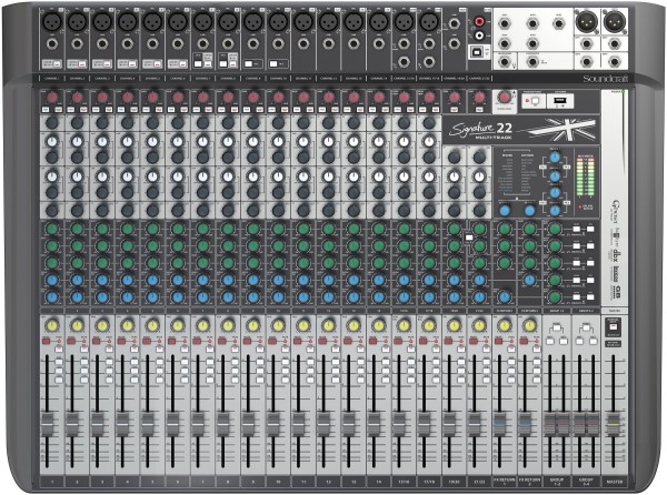 |
SOUNDCRAFT SIGNATURE 22 MTK MIXER:
The SOUNDCRAFT SIGNATURE 22 MTK mixer allows you to simultaneously control and send, any (one or more) of twenty-two sound sources to
In a sort
of technical short-hand, this mixer may referred to as a 22:4:2 mixer
(with 5 auxiliaries) to indicate it offers 22 inputs, 4 group outputs,
and 2 main outputs (with 5 auxiliaries). Although
the mixer may appear to be complicated, it is in fact, composed of only
a few different building blocks, called modules or strips. Each type
of strip groups together all the controls and internal circuitry to
perform similar functions. On this mixer, there are two kinds of INPUT strips, 14 MONO and 6 STEREO. The INPUT strips are grouped together on the left side of the mixer. The AUX/GROUP/MASTER strip is on the extreme right. You will only need to learn the operation of these few strips,
|
| ------------------------------------ INPUTS ---------------------------------- | OUTPUTS | |||
| MONO | STEREO | |||
| CHANNELS 1-14 | CHANNELS 15-18 | CHANNELS 19-20 | FX RETURN | AUX/GROUP/MASTER |
 |
 |
 |
 |
 |
| CHANNELS 1-14 | CHANNELS 15-18 | CHANNELS 19-22 | FX RETURNS | AUX/GROUP/MASTER |
| MONO | STEREO | |||
| ------------------------------------ INPUTS ---------------------------------- | OUTPUTS | |||
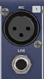
| MONO INPUT STRIP |
||
| MONO inputs are used to connect to sources with a single output -- microphones, guitars. |
||
|
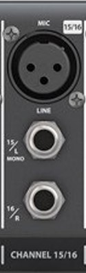
Audio signal levels can fall into one of two broad categories.
Microphone level signals connect to the three-pin XLR-type female connectors. Line level signals connect to the 1/4 inch TRS jacks. Either type of signal must be connected to the mixer via the appropriate jack or socket, tp avoid undesireably deteriorating the quality of the signal. DO NOT connect active signals to both sockets on the same input channel. |
 |
|
|
|
 |
|
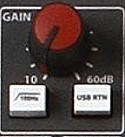
GAIN/100 Hz/USB RTN
|
||
The 100Hz (High Pass -- Low Cut Filter) button allows you to remove unwanted low-frequency noise from the input signal.
|
||
The USB RTN (Universal Serial Bus Return) allows you to choose between the analog channel input and the digital signal from a computer. |
||
LIMITER
|
 |
|
| HI-Z | ||
The HI-Z button causes the LINE TRS jack to appear electrically similar to the input jack on a guitar amplifier. This can allow you to record an instrument like an electric guitar by connecting it directly to the console. |
 |
|
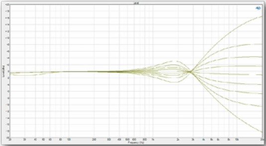
| EQUALISER | ||
The EQ (EQualiser) section of the input strip allows you to adjust the tonal qualities of the input signal. The EQ is to sound, what coloured "gels" are to lighting. |
||
 |
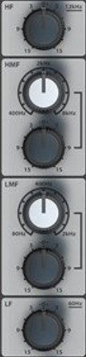
HF:
(High Frequency)
Shelving |
 |
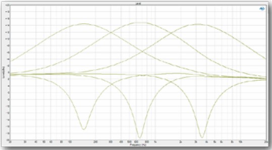 |
HMF: (High Mid Frequency)
|
|
|
LMF: (Low Mid Frequency)
|
|
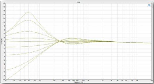 |
LF: (Low Frequency) Shelving |
|
|
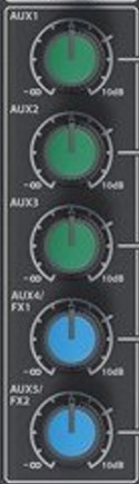
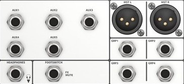
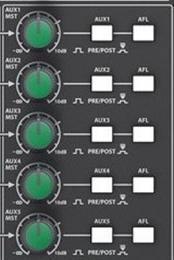
AUXILLIARY SENDS 1-5
|
||
The
controls labeled AUX (AUXilliary) allow you
to send a part of the signal from any input channel strip to any of
three additional outputs. These outputs can be used to feed a separate
mix to program sound, monitors onstage, headphones in the studio, or to
the sound processing and effects devices in the control room.
AUX sends
can be taken before or after the channel fader. We call these
feeds PRE fader or POST
fader. POST
fader sends are used to feed reverb devices where you would want the
strength of the reverb effect to follow the level as controlled by the
channel fader. PRE
fader sends are used to feed headphones or stage monitors. You wouldn't
necessarily want the mix in the headphones to change as you
adjust the recording or house levels.
On
the SIGNATURE 22 MTK:
AUX
1-5 sends can be switched to be either PRE or POST and used
to
feed external equipment. (see AUX MASTER below.)
AUX 4 and 5 sends are used to feed the internal Effects Processors, POST fader, as well.. |
 |
|
| |
||
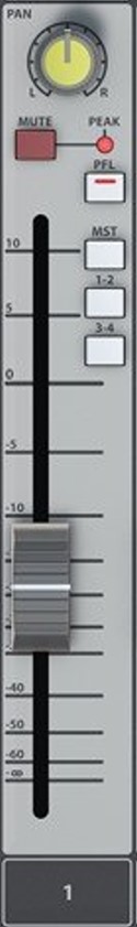
| PAN/MUTE/PFL/CHANNEL
FADER The PAN
control (short for panoramic potentiometer) allows you to send the
signal anywhere in the sound field between the
selected left and right outputs.
The MUTE button cuts-off (mutes) the input signal from the selected outputs. The PFL (Pre-Fade Listen) button sends the input signal directly to the left/right LED meters and the headphones. A red LED (AFL/PFL ACTIVE), just below the meters indicates that at least one PFL button is pressed. If
you press the MST
(MaSTer) button and pan fully left; the signal will go only to
the left MASTER output. Panning right will assign
the
signal to only the right
MASTER output. Midway
between left and right will assign the signal somewhere between.
Odd numbered inputs and outputs are arbitrarily considered as left and the even numbered ones as right. If you press the 1-2(GROUP 1-2) button and pan fully left; the signal will go only to the GROUP 1 output. Panning right will assign the signal to only the right GROUP 2 output. Midway between left and right will assign the signal somewhere between. The sliding control with the white marker is the input channel fader. This is your operational control over the signal level during a recording or performance. It allows you to smoothly fade an individual sound in or out. At the -0- setting of the channel fader, there is still 10 dB of gain available, should the input signal drop in level. We say that there is 10 dB of gain-in-hand. This gives you room to maneuver should the input signal change. Working at -0- on the channel fader also allows for smooth fades in or out. |
 |
|
| STEREO INPUT STRIPS |
|
|
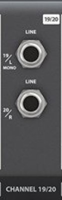
On the SIGNATURE 22 MTK, input channels 15/16, 17/18, 19/20 and 21/22 are STEREO input channels. |
 |
STEREO channel 19/20 has no microphone level input, and the line level input is on a pair of TRS sockets. |
 |
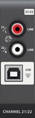
STEREO channel 21/22 has no microphone level input, and the analog line level input is on a pair of RCA sockets. |
 |
On the SIGNATURE 22 MTK, what you might think would be input channels 23/24 and 25/26 get their signal from the internal effects processors, and are labelled FX RETURN 1 and 2. |
|
Most of the other controls on a STEREO Input strip are identical to those on a MONO Strip. Two exceptions -- |
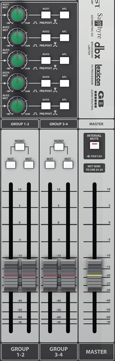
| AUX/GROUP/MASTER OUTPUTS | ||
|
 |
|
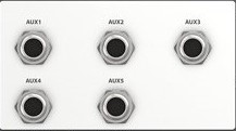
| AUX MASTER STRIP | ||
The AUX1-5 MST (MaSTer) controls set the level of signals sent to the AUX1-5 SEND busses and to the AUX 1-5 TRS output connectors. |
 |
 |
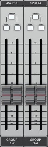
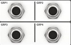
| GROUP MASTER STRIP | ||
|
 |
 |
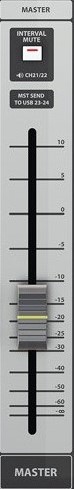
| MASTER STRIP | ||
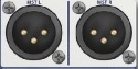
The MASTER fader sets the level of signals sent to the Master buss, and to the MST L and to the MST R XLR output connectors. |
 |
 |
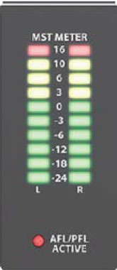
| METERS | ||
The meters on the Signature 12MTK show Master Left/Right output level in normal operation. When any SOLO button on the console is depressed, the "AFL/PFL" will light to indicate this condition. |
 |
|
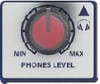
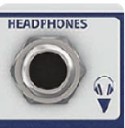
| HEADPHONES | ||
The headphone signal is always the Master Stereo Output unless a Solo (PFL or AFL) is activated. |
 |
 |
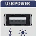
| USB POWER | ||
This USB Type-A socket is for attaching a USB-powered LED lamp - NOT for recharging your phone. |
 |
|
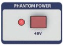
| GLOBAL PHANTOM POWER | ||
|
 |
|
| |
||
| ADDITIONAL
LINKS |
||
|
Soundcraft Signature -- Lexicon Effects -- Notes on the Soundcraft Signature built-in FX Processor Soundcraft Signature 22 MTK Preset Outline -- Print out this reduced-contrast image to mark the "preset" positions of the controls on the Soundcraft console. Soundcraft Signature 22 MTK -- Owner's Manual -- Read this attentively to really understand the mixer's operation. Soundcraft Signature MTK -- Recording Guide -- How to use the USB sound device on both Signature 12 MTK and 22 MTK consoles. |